




Introduction
A fuse is a safety component that protects an electrical circuit from excessive current. A fuse symbol represents this component in a circuit diagram and helps readers identify its position and protection function.
This article explains how fuses work, the meaning of different fuse symbols, international symbol standards, common fuse markings, and how to identify fuse symbols in circuit diagrams.
What Is a Fuse?
A fuse is an electrical protection device that stops current flow when the current becomes too high. It usually contains a thin metal element inside an insulating body. When excessive current generates too much heat, the metal element melts and opens the circuit.
Fuses help prevent damage to wires and electrical equipment. Most traditional fuses work only once and must be replaced after they blow.

Function
A fuse performs several important functions in an electrical circuit:
- Overcurrent Protection: Stops excessive current before it causes serious damage to circuit components.
- Short-Circuit Protection: Disconnects the circuit when a short circuit causes a sudden rise in current.
- Fire Prevention: Reduces the risk of overheating that may lead to electrical fires.
- Equipment Protection: Helps protect electrical devices, wires, and other components from excessive current.
- Circuit Isolation: Breaks the electrical path when the fuse element melts.
How Does a Fuse Work?
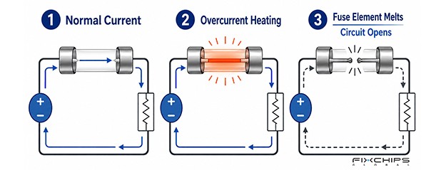
A fuse contains a metal element that carries current during normal operation. When the current exceeds its designed limit for a sufficient time, heat builds up in the element until it melts.
Once the metal element melts, the electrical path is broken and current stops flowing. This helps protect the rest of the circuit from excessive current.
Applications
Fuses are used in many electrical and electronic systems:
- Household Appliances
- Automotive Systems
- Power Supplies
- Industrial Equipment
- Electronic Devices
What Is a Fuse Symbol?
A fuse symbol is a graphical representation of a fuse in an electrical or electronic circuit diagram. It shows where the fuse is connected and indicates that the circuit has overcurrent protection.
Why Does a Fuse Symbol Matter?
Fuse symbols make circuit diagrams easier to read and understand. They provide several benefits:
- Easy Identification: Helps readers quickly locate fuses in a circuit diagram.
- Circuit Understanding: Shows where overcurrent protection is placed in the electrical path.
- Design Communication: Helps engineers and technicians understand the circuit design.
- Troubleshooting: Makes it easier to identify the fuse that may need inspection or replacement.
- Standardization: Provides a common way to represent protection devices in technical drawings.
International Standards for Fuse Symbols
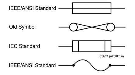
Different countries and industries may use different graphical forms to represent fuses. The following standards provide common references for drawing and reading these symbols.
|
Standard |
Organization |
Main Use |
|
IEC 60617 |
International Electrotechnical Commission (IEC) |
International use |
|
IEEE 315 |
Institute of Electrical and Electronics Engineers (IEEE) |
North American |
|
ANSI Y32.2 |
American National Standards Institute (ANSI) |
United States |
|
CSA Z99 |
Canadian Standards Association (CSA) |
Canada |
Types of Fuse Symbols
Fuses have different structures and operating characteristics. Their symbols help readers identify their functions and understand how they protect a circuit.
General Fuse Symbol

A general fuse is a one-time protection device. It contains a metal element that melts when excessive current produces enough heat, breaking the circuit.
Its IEC symbol consists of a central rectangle placed along a straight conductor line, with two vertical inner lines positioned near its ends to divide the box into three sections.
Fast-Blow Fuse Symbol

A fast-blow fuse is designed to open quickly when excessive current occurs. It is commonly used to protect sensitive electronic components that cannot withstand high current for long.
It’s symbol is similar with general fuse symbol, but adds a small solid circle located inside the right end section.
Slow-Blow Fuse Symbol

A slow-blow fuse, also called a time-delay fuse, allows short periods of higher current without opening immediately. It is often used in circuits with motors and transformers that draw extra current during startup.
Its circuit symbol is also familiar with the general fuse symbol, but adds two small solid circles located inside the right end section.
Thermal Fuse Symbol

A thermal fuse is a temperature-sensitive protection device. It opens the circuit when the surrounding temperature reaches its designed operating limit, helping prevent overheating.
Its symbol consists of a central rectangle placed along a straight conductor line, with a diagonal line running from the bottom-left corner to the top-right corner inside the box, and a t⁰ symbol positioned underneath the rectangle.
Fuse Switch Symbol
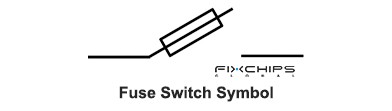
A fuse switch combines a fuse and a switching function in one device. It can protect a circuit from excessive current and provide a way to connect or disconnect the electrical supply.
Its symbol combines the fuse representation with a switch or isolating contact. This shows that the device provides both circuit protection and switching.
Fuse with Alarm Contact Symbol
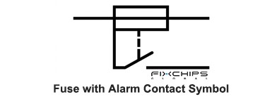
A fuse with an alarm contact provides a signal when the fuse operates. When the fuse blows, the alarm contact changes its state and can activate an external warning or monitoring circuit.
Its symbol includes a fuse element and an additional contact connection, typically a small circle or extension. The extra contact represents the alarm function and distinguishes it from a general fuse.
Oil Type Fuse Symbol
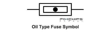
An oil type fuse is a high-voltage fuse arrangement used in electrical power systems. Its fuse element operates inside an oil-filled insulating environment, which helps control the electrical arc when the fuse opens.
Its symbol consists of a central rectangle placed along a straight conductor line, containing a nested inner rectangle and a small solid circle located right in the center.
Striker Fuse Symbol
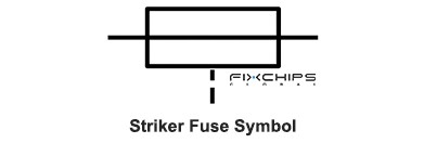
A striker fuse has a built-in mechanical striker that moves when the fuse element operates. This movement can activate a switch or another mechanical device, helping disconnect other parts of the circuit.
Its symbol includes the basic fuse representation and an additional mechanical linkage. The extra line or connection indicates that the fuse can trigger a mechanical action.
Decoding Fuse Markings
Fuse markings provide important information about the fuse's operating limits and characteristics. Understanding these markings helps readers identify the correct fuse for a circuit.
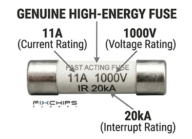
|
Marking |
Description |
|
A (Ampere) |
Indicates the rated current that the fuse can carry under specified conditions. |
|
V (Volt) |
Shows the rated voltage at which the fuse is designed to operate. |
|
AC |
Indicates that the fuse is rated for alternating current. |
|
DC |
Indicates that the fuse is rated for direct current. |
|
F |
Commonly indicates a fast-acting fuse. |
|
T |
Commonly indicates a time-delay fuse. |
|
I.R. / A.I.R. |
Indicates the interrupting or ampere interrupting rating of the fuse. |
|
Manufacturer Code |
Identifies the manufacturer or product series. |
How to Identify a Fuse Symbol in a Circuit
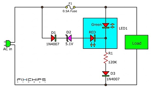
You can identify a fuse symbol by examining its shape, position, and nearby markings. Follow these steps:
1. Find the Symbol: Look for a small rectangle or another recognized fuse representation placed along a circuit line.
2. Check Its Position: See whether the symbol is connected in series with the power supply and the protected circuit.
3. Read Nearby Labels: Look for reference labels such as F1 or FU1, which may identify the fuse.
4. Check the Ratings: Read the current and voltage values written next to the symbol to understand its electrical limits.
5. Identify Its Type: Check for markings such as F, T, PTC, or other descriptions that indicate its operating characteristics.
Common Applications of Fuse Symbols in Circuits
Fuse symbols appear in many practical electrical circuits. They show where overcurrent protection is installed and which components are protected.
Automotive Headlight Circuit
A fuse is connected between the vehicle battery and the headlight circuit. In many vehicles, separate fuses protect the left and right headlights.
When excessive current occurs, the fuse opens the circuit and protects the headlight wiring and related components.
AC Power Supply Circuit
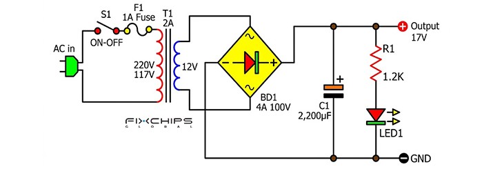
A fuse is commonly placed at the AC input of a power supply, before the main power conversion components. It protects the power supply from excessive current caused by faults or short circuits.
If a fault causes excessive current, the fuse opens and disconnects the input power.
Household Appliance Heating Circuit
A thermal fuse can be connected in series with the heating element of an appliance, such as an electric kettle. It opens the circuit when the temperature reaches its specified limit.
This helps prevent excessive heating and reduces the risk of damage to the appliance.
Industrial Motor Control Circuit
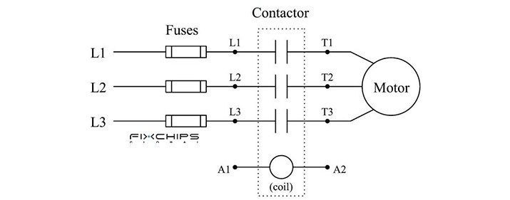
In an industrial motor circuit, fuses are commonly installed in the three-phase power lines before the contactor and motor. They provide short-circuit protection for the motor circuit and its wiring.
When a short circuit occurs, the affected fuse opens and interrupts the power supply.
Fuse Symbol vs Resistor Symbol
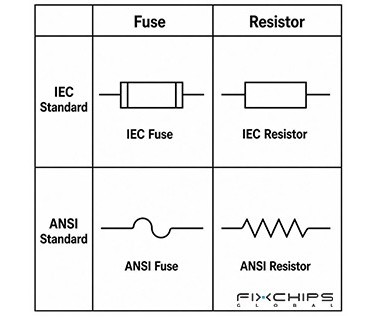
A fuse symbol and a resistor symbol may look similar in some circuit diagrams because both can include a rectangular shape. However, they represent different components and have different functions.
A fuse protects a circuit by breaking the current path when excessive current occurs. A resistor controls current by providing electrical resistance and normally remains connected during operation.
|
Comparison |
Fuse |
Resistor |
|
Symbol Style |
A rectangle with a straight line passing through it in IEC diagrams. |
A rectangle in IEC diagrams or a zigzag line in common American diagrams. |
|
Main Function |
Protects the circuit from excessive current. |
Limits current or creates a voltage drop. |
|
Circuit Role |
Opens the circuit when its operating limit is exceeded. |
Provides resistance while remaining in the circuit. |
|
Working Principle |
The fuse element melts and interrupts current flow. |
The resistor converts part of the electrical energy into heat. |
|
Replacement |
A one-time fuse must be replaced after it operates. |
Usually remains in place unless damaged or changed during maintenance. |
|
Common Applications |
Power supplies, automotive systems, and electrical equipment. |
Voltage dividers, current limiting, and signal circuits. |
Frequently Asked Questions
What is a fuse and its symbol?
A fuse is an overcurrent protection device that interrupts current when it exceeds a specified level for a sufficient time. In IEEC circuit diagrams, its general symbol is a small rectangle with a straight conductor line passing through it.
How does a fuse work?
When excessive current flows, heat builds up in the fuse element until it melts. This breaks the electrical path and stops current from flowing through the circuit.
What dose a fuse do?
A fuse protects electrical circuits from overloads and short circuits. It disconnects the power supply when excessive current occurs, helping prevent damage to wires and equipment.
Is a fuse the same as a diode?
No. A fuse is a protection device that interrupts a circuit when excessive current occurs. A diode is a semiconductor component that mainly allows current to flow in one direction and blocks it in the opposite direction under normal operating conditions.
What does the 80% fuse sizing rule mean?
The 80% rule is a common design guideline that recommends keeping the normal operating current at or below 80% of the fuse's rated current under specified conditions.
For example, a 10A fuse is generally recommended for a continuous operating current of no more than 8A under the stated conditions.
Where can you typically find fuses in electrical systems?
Fuses are commonly installed near power inputs, on circuit boards, and in electrical distribution systems. They are also used in automotive circuits, household appliances, power supplies, and industrial equipment.
What is the typical service life of an electrical fuse?
A fuse does not have a fixed replacement schedule when it operates within its design limits. Modern fuses can remain in service for many years, but they must be replaced after they open due to excessive current.


