



A diode is a semiconductor device that mainly allows current to flow in one direction. This guide explains what a diode is, how it works, how to read common diode symbols, and how to identify and test diodes in circuits.
What Is a Diode?
A diode is a semiconductor device with two terminals: the anode and the cathode. It is commonly used to control current direction, such as allowing current to pass in one direction while limiting it in the other. Most basic diodes are made from semiconductor materials such as silicon and use a PN junction as their main structure.
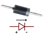
The anode is connected to the P-type side, while the cathode is connected to the N-type side. The cathode is usually marked by a band on the physical diode, which matches the bar in the circuit symbol.
Electrical Characteristics of a Diode
Voltage and Current Relationship
The current through a diode depends strongly on the voltage applied across it.
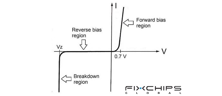
In forward bias, the anode is more positive than the cathode, the diode conducts current, and its forward voltage drop becomes significant.
In reverse bias, the diode normally allows only a very small leakage current until its reverse-voltage limit is reached.
In simple circuit analysis, a silicon diode is often described as having a forward voltage of about 0.7 V, but the actual value changes with diode type, current, temperature, and construction.
Resistance
A diode does not behave like a fixed resistor. In forward bias, it has much lower resistance to current than in reverse bias, while reverse bias produces a very high resistance under normal operating conditions.
Working Principle of Diodes
A basic diode is formed from a PN junction. The P-type region has holes as its main charge carriers, while the N-type region has electrons as its main charge carriers. Where the two regions meet, a depletion region forms and acts as a barrier to charge movement.
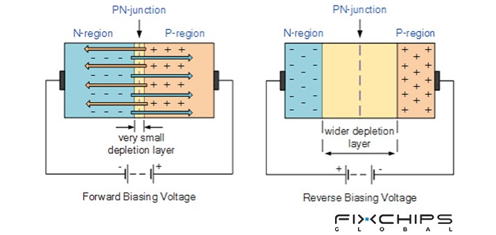
When voltage is applied, the depletion region changes. In forward bias, the applied voltage reduces the barrier and allows charge carriers to cross the junction, so current can flow. In reverse bias, the depletion region becomes wider and strongly limits current flow.
A simple way to picture this is to think of the diode as a one-way gate. The gate opens more easily in the forward direction and remains almost closed in the reverse direction.
What Is a Diode Symbol?
A diode symbol is a simple graphic used to represent a diode in a circuit diagram. It shows the basic structure and current direction without requiring the physical diode to be drawn.
Different diode types use modified versions of the basic symbol. These changes help readers identify the special function of each diode.

Why Use a Symbol to Represent a Diode?
- Saves space: A small symbol can replace a detailed physical drawing.
- Shows direction: The symbol helps identify the anode and cathode.
- Shows function: Modified symbols can indicate special diode types.
- Improves readability: Standard symbols make circuit diagrams easier to understand.
- Supports circuit design: Engineers can show how components are connected without drawing their physical appearance.
Standard Diode Symbol
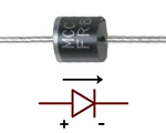
A standard diode is mainly used to control the direction of current in a circuit. Its symbol consists of a triangle-shaped arrow-like section and a vertical bar, with the bar marking the cathode; the symbol also shows the direction in which conventional current flows.

Diode Symbol Analysis
- Anode (+): The anode is on the left side and is represented by triangle-shaped arrow-like section in the symbol. It is the positive terminal when the diode is forward-biased.
- Cathode (-): The cathode is on the right side and is represented by the vertical bar in the symbol. It is the negative terminal when the diode is forward-biased.
- Current Direction: Conventional current flows from the anode to the cathode when the diode is forward-biased.
Zener Diode Symbol
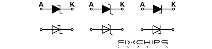
A Zener diode is designed to operate in reverse bias within its specified breakdown region. It is commonly used for voltage reference and voltage regulation because its reverse-voltage behavior can provide a relatively stable voltage.
Its symbol is based on the standard diode symbol, but the cathode line is drawn with a distinctive bent or angled shape. This modified line makes the Zener diode easier to distinguish from a standard diode in a circuit diagram.
Schottky Diode Symbol
A Schottky diode is commonly used where fast switching and a low forward voltage drop are useful. Unlike a basic PN-junction diode, it uses a metal-semiconductor junction.
The Schottky symbol is based on the standard diode symbol but has a modified cathode marking. The extra shape around the cathode line helps distinguish it from a standard PN-junction diode.

Light & Detection Diode Symbol
Some diodes interact with light. They can produce light, detect light, or generate laser light. Their circuit symbols add arrows to the basic diode symbol to show the relationship between the diode and light.
Light Emitting Diode (LED) Symbol
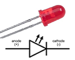
A Light Emitting Diode (LED) produces light when it is forward-biased and current flows through it. LEDs are widely used for indicators, displays, and lighting.
The LED symbol uses the basic diode symbol with two arrows pointing outward. The arrows show that light is emitted from the device.

Photo Diode Symbol
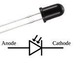
A photo diode is designed to respond to light. When light reaches the device, it can produce an electrical current, so photo diodes are widely used for light detection and sensing.
Its symbol uses the basic diode symbol with two arrows pointing toward the diode. The arrows represent incoming light.

Laser Diode Symbol
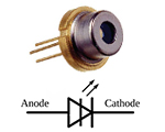
A laser diode is a semiconductor diode that produces laser light when it operates under the proper conditions. It is used in applications that require a focused and coherent light source.
The laser diode symbol is often similar to the LED symbol, with arrows pointing outward to show emitted light. Because the symbols can be similar, the component name or circuit documentation is important when identifying the exact device.

Common Diodes and Their Functions
The following table summarizes several common diode types and their main functions.
|
Type |
Image |
Function |
|
Standard Diode |
|
Allows current to flow mainly in one direction |
|
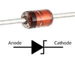
Zener Diode |
|
Used for voltage regulation and voltage reference |
|
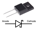
Schottky Diode |
|
Provides fast switching and a low forward voltage drop |
|
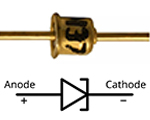
Tunnel Diode |
|
Uses quantum tunneling and is designed for very fast switching and high-frequency applications. |
|
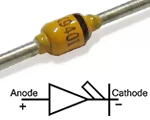
PIN Diode |
|
Uses a P-I-N structure and is commonly used for RF switching, signal control, and detection. |
|
Fast Recovery Diode |
|
Designed to recover quickly after forward conduction and is commonly used in high-frequency switching and power circuits. |
|
LED |
|
Converts electrical energy into light. |
|
Photo diode |
|
Detects incoming light and converts it into an electrical response. |
|
Laser Diode |
|
Produces laser light for optical and communication applications. |
How to Identify a Diode Symbol in a Circuit
|
Step |
Description |
|
1. Find the basic diode shape |
Look for the main diode symbol in the circuit. This gives you the starting point for identification. |
|
2. Locate the cathode |
Find the bar or modified bar in the symbol. In a basic diode, this side is the cathode. |
|
3. Locate the anode |
The opposite terminal is the anode. In a basic PN diode, it corresponds to the P-type side. |
|
4. Check for extra marks |
Look for bent cathode lines or other special markings. These changes can identify types such as Zener or Schottky diodes. |
|
5. Look for light arrows |
Arrows pointing outward usually indicate light emission, as in an LED. Arrows pointing inward indicate incoming light, as in a photodiode. |
|
6. Check the circuit label |
If the symbol is unclear, check the component label or circuit documentation. This is especially useful when two diode types have similar symbols. |
Diodes in a Circuit
A diode can be installed in two basic bias conditions. The direction of the applied voltage determines how the diode behaves.
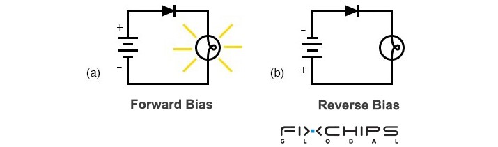
Forward Bias
- The anode is more positive than the cathode.
- The applied voltage reduces the PN-junction barrier.
- The depletion region becomes narrower.
- Current can flow through the diode when the applied voltage is sufficient.
- This condition is used when the circuit needs the diode to conduct.
Reverse Bias
- The cathode is more positive than the anode.
- The applied voltage increases the PN-junction barrier.
- The depletion region becomes wider.
- Only a small leakage current normally flows.
- If the reverse voltage becomes too high, breakdown can occur.
Applications of Diodes
Diodes are used in many circuits because they can control the direction of current and respond to voltage or light.
- AC-to-DC rectification: Diodes allow current to pass during the required part of an AC waveform, helping convert AC into pulsating DC.
- Reverse-polarity protection: A diode can be arranged to prevent current from flowing through a circuit when the power source is connected with the wrong polarity.
- Voltage regulation: Zener diodes can operate in reverse breakdown to provide a stable voltage reference in suitable circuits.
- High-speed switching: Schottky diodes are useful in circuits where fast switching and low forward voltage are important.
- Light indication: LEDs convert electrical current into visible or other forms of light and are used in indicators and displays.
- Light detection: Photo diodes convert incoming light into an electrical response and are used in light-sensing circuits.
- Laser light generation: Laser diodes produce laser light and are used in systems that require a laser source.
How to Test a Diode with a Multimeter?
A digital multimeter can be used to check whether a diode shows the expected forward and reverse behavior. The diode-test mode is generally the preferred method for this test.

1. Turn off the circuit power
Make sure the circuit is not energized before testing. If necessary, discharge capacitors because stored voltage can affect the measurement.
2. Set the multimeter to diode-test mode
Select the diode symbol on the meter. This mode applies a small test voltage and measures the voltage drop across the diode.
3. Test in forward bias
Place the red probe on the anode and the black probe on the cathode. A good silicon diode commonly shows a forward voltage drop around 0.5–0.8 V, although the actual value depends on the diode and test conditions.
4. Test in reverse bias
Reverse the probes: place the red probe on the cathode and the black probe on the anode. A good diode normally shows OL or a similar over-range indication, meaning that the meter detects very high resistance in this direction.
5. Compare both readings
A normal diode should show a forward voltage in one direction and a blocked or very high-resistance condition in the other. If the meter shows conduction in both directions or OL in both directions, the diode may be faulty.
Frequently Asked Questions
What Is a Diode, and How is it represented?
A diode is a semiconductor device with two terminals called the anode and cathode, and it is commonly used to control current direction. Its circuit symbol uses triangle-shaped arrow-like section with a line marking the cathode, providing a simple way to represent the component in a schematic.
What does a diode do in a circuit?
A diode mainly controls the direction of current in a circuit. It allows current to flow more easily in the forward direction while strongly limiting current in the reverse direction under normal conditions.
Which terminal of a diode is positive?
The anode is the positive terminal in the usual forward-bias arrangement, while the cathode is the negative terminal. In a diode symbol, the cathode is identified by the bar, which also corresponds to the marked end of many physical diodes.
How is a Zener diode symbol different from a standard diode symbol?
A Zener diode symbol is based on the standard diode symbol but has a modified, bent cathode line. This distinctive line helps identify it in a circuit diagram and indicates that it is a Zener diode rather than a standard diode.
How can we distinguish between LED symbols and standard diode symbol?
An LED uses the basic diode symbol but adds two arrows pointing outward from the diode. These arrows represent the light emitted by the LED when it operates in the forward direction.


