



Introduction
An inductor is a passive electronic component that stores energy in a magnetic field when current flows through it. In circuit diagrams, an inductor symbol gives engineers a simple way to show where an inductor is used and what type of component it represents.
This guide explains what an inductor does, how it works, what its symbol means, and how to identify it in circuit diagrams.
What Is an Inductor?
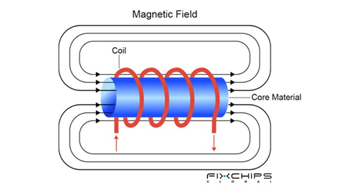
An inductor is usually made from a wire wound into a coil. When current flows through the winding, it creates a magnetic field around the coil. An inductor resists rapid changes in current and can store energy in its magnetic field.
What Does an Inductor Do?
An inductor can perform several important functions in a circuit:
- Store energy: It stores electrical energy in its magnetic field.
- Resist sudden current changes: Its voltage is related to how quickly the current changes.
- Filter signals: Inductors can work with capacitors to filter unwanted parts of a signal.
- Reduce high-frequency noise: Chokes and related inductive components can be used to suppress unwanted high-frequency signals.
- Support power conversion: Inductors are widely used in switching power supplies and DC-DC converters.
Applications of Inductors
Inductors appear in many types of electronic equipment:
- Power supplies
- Filters
- RF circuits
- EMI filtering
- Transformers and coupled circuits
How Does an Inductor Work?
When current flows through an inductor, the winding produces a magnetic field. If the current changes, the magnetic field also changes, producing an induced voltage that opposes the change in current.
A simple way to understand this is to think of an inductor as a component that does not like current to change too quickly. A larger inductance means a stronger response to a given rate of current change.
Key Parameters of an Inductor
Inductance is important, but it is not the only specification that matters when selecting an inductor. Designers also consider current, resistance, frequency, tolerance, and temperature.
|
Parameter |
Description |
Typical Values/Units |
|
Inductance |
The main electrical value that describes how strongly the component responds to changes in current. |
H, mH, μH, nH |
|
Inductance Tolerance |
Shows how far the actual inductance may differ from its stated value. | ±%, such as ±5%, ±10%, ±20% |
|
Rated Current |
Indicates the current level associated with the manufacturer's specified operating condition. |
A or mA |
|
DC Resistance (DCR) |
The resistance of the winding when measured with direct current. | Ω, mΩ |
|
Self-Resonant Frequency (SRF) |
The frequency at which the inductor's parasitic capacitance causes resonant behavior. |
Hz, kHz, MHz, GHz |
|
Operating Temperature |
The temperature range in which the component is specified to operate. | °C |
|
Quality Factor (Q) |
A measure used to describe inductor performance, especially in high-frequency applications. |
Dimensionless |
What Is Inductance?
Inductance describes an inductor's ability to oppose changes in current and is measured in henries (H). In practical components, values are often expressed in millihenries (mH), microhenries (μH), or nanohenries(nH).
For an ideal long solenoid, inductance can be expressed as:

Where:
L = inductance
μ = permeability of the magnetic material
N = number of turns in the winding
A = cross-sectional area of the coil
l = length of the magnetic path or coil, depending on the model used
This equation describes an idealized solenoid. Real inductors can have more complex structures, so their actual inductance depends on their construction and operating conditions.

Several physical factors affect inductance:
- Number of turns: More turns generally increase inductance in the ideal solenoid model.
- Core material: A magnetic core can increase the inductance compared with an air-core structure.
- Coil area: A larger cross-sectional area increases inductance in the ideal solenoid model.
- Coil length: Increasing the coil length reduces inductance in the ideal solenoid model.
- Operating conditions: The measured inductance of a real component can change with frequency, current, and temperature.
What Is an Inductor Symbol?
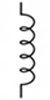
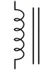
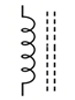
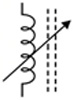
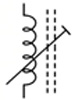
An inductor symbol is the graphical representation used to identify an inductor or winding in a circuit diagram. The basic symbol is drawn as a series of curved loops, representing the coil or winding. Additional marks can be used to show features such as a magnetic core or adjustable inductance.
The symbol does not show every physical detail of the real component. Instead, it gives the reader the essential information needed to understand the circuit.

Why Use a Symbol for an Inductor?
Using an inductor symbol provides several advantages:
- Makes schematics easier to read: A simple symbol takes less space than a physical drawing.
- Shows the component type: The coil shape quickly identifies an inductive component.
- Shows special features: Extra marks can indicate a magnetic core, adjustment, or other construction details.
- Supports standardized communication: Standardized graphical symbols help engineers interpret circuit diagrams consistently.
International Standards for Inductor Symbols
Inductor symbols are covered by established graphical-symbol standards. The following standards are especially relevant when reading electrical and electronic diagrams.
|
Standard |
Organization |
Description |
|
IEC 60617 |
International Electrotechnical Commission (IEC) |
Provides graphical symbols for diagrams. Its symbol database includes the general coil/winding symbol and specific inductor symbols, such as magnetic-core and variable inductors. |
|
IEEE Std 315 |
Institute of Electrical and Electronics Engineers (IEEE) |
Defines graphical symbols for electrical and electronic diagrams, including inductors, magnetic-core inductors, adjustable inductors, and transformers. |
|
ANSI Y32.2 |
American National Standards Institute (ANSI) |
Provides graphical symbols for electrical and electronic diagrams and includes a section covering transformers, inductors, and windings. |
Types of Inductor Symbols
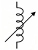
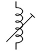
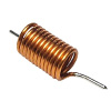
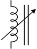
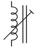
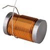
The most common inductor symbols found in circuit diagrams include various variations based on core material—such as air-core, iron-core and ferrite-core—as well as adjustability, including fixed, variable, and preset inductors.
Common Inductors
|
Inductor Type | Fixed Inductor |
Variable Inductor |
Preset Inductor |
Product Image |
|
Air Core |
|
|
|
|
|
Iron Core |
|
|
|
|
|
Ferrite Core |
|
|
|
|
Special Inductors
Besides common fixed and adjustable inductors, circuit diagrams may also contain special inductive components. Two important examples are coupled coils and transformers.
Coupled Inductive Coils
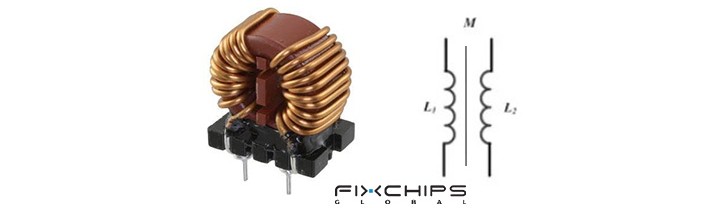
Coupled coils are two or more windings that share magnetic flux. A current change in one winding can produce a voltage in another winding through mutual inductance.
Their symbol normally shows two coil symbols placed close to each other. A line or pair of lines between the windings may be used to show a shared magnetic core, depending on the type of component and the drawing standard.
Iron-Core Transformer
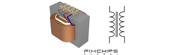
A transformer uses two or more windings coupled through a magnetic field. The windings are not normally connected directly to each other; energy is transferred through magnetic coupling.
In a circuit diagram, a transformer is commonly drawn as two coil symbols facing each other. Parallel lines between the coils indicate a magnetic core when the core needs to be shown.
How to Identify an Inductor Symbol in a Circuit
When reading a circuit diagram, you can identify an inductor by following these simple steps:
1. Look for the coil shape: The basic inductor symbol is drawn as a series of curved loops.
2. Check the component label: Inductors are commonly identified with the reference letter L in circuit diagrams.
3. Look for extra marks: Lines beside the coil may indicate a magnetic core, while an arrow can indicate adjustability.
4. Check the surrounding circuit: Inductors often appear in power, filtering, RF, or signal circuits.
5. Read the value: A value such as μH or mH next to the symbol usually indicates the inductance.
Practical Examples of Inductor Symbols in Circuit Diagrams
The same basic inductor symbol can appear in different circuits. Its function depends on how it is connected and what other components surround it.
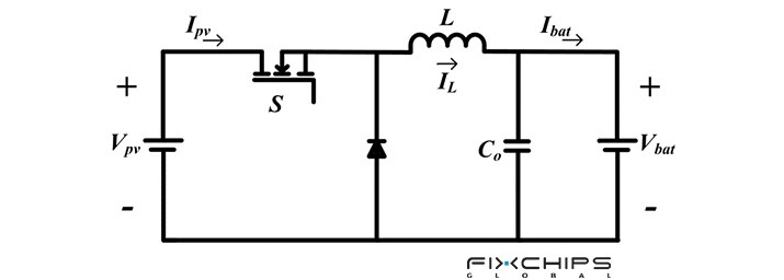
- Power supply circuits: Inductors are used in switching converters to store energy and control current ripple. They are important parts of many DC-DC converter designs.
- LC filter circuits: An inductor can be combined with a capacitor to form a filter. The circuit uses the frequency-dependent behavior of these components to reduce unwanted signal components.
- RF circuits: Inductors can be used in tuning and impedance-matching circuits. At high frequencies, parameters such as Q factor and self-resonant frequency become especially important.
- EMI and noise filters: Inductive components such as chokes can be used to reduce unwanted high-frequency noise on power or signal lines.
Inductor Symbols vs Other Symbols
An inductor symbol can be confused with other passive-component symbols when reading a circuit for the first time. The easiest way to tell them apart is to look at their shape and basic function.
Inductor vs. Capacitor
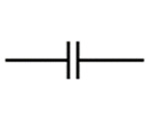
An inductor is normally shown as a coil or series of loops. A capacitor is normally shown as two plates separated by a gap. Their electrical behavior is also different: an inductor stores energy in a magnetic field, while a capacitor stores energy in an electric field.
Inductor vs. Resistor
An inductor uses a coil-shaped symbol, while a resistor uses a rectangle or a zigzag line. Their functions are also different: a resistor mainly limits current and dissipates electrical energy as heat, while an inductor stores energy in a magnetic field and opposes changes in current.
Inductor vs. Resistor vs. Capacitor
|
Component |
Symbol Style |
Main Function |
|
Inductor |
Coil or curved loops
|
Stores energy in a magnetic field |
|
Resistor |
Rectangle or zigzag
|
Limits current |
|
Capacitor |
Two conductive plates
|
Stores energy in an electric field |


Frequently Asked Questions
What is an inductor and how does it work?
An inductor is a passive electrical component that provides inductance through a coil or winding. When current changes through the coil, it produces an induced voltage that opposes the change in current.
What is an inductor used for in a circuit?
An inductor opposes changes in current and can store energy in its magnetic field. It is commonly used in circuits for functions such as filtering, energy storage, and controlling current changes.
How can you determine the inductance of a coil?
For an ideal solenoid, inductance can be calculated using L = μN²A/l, where N is the number of turns, μ is the permeability of the core material, A is the cross-sectional area, and l is the coil length. The actual inductance of a manufactured inductor can also depend on its construction and operating conditions.
What does an inductor symbol look like?
A basic inductor is represented by a series of curved loops that resemble a coil of wire. Additional marks can be used to indicate features such as a magnetic core or adjustable inductance.
Are inductors polarized components?
A basic inductor generally does not have a fixed positive or negative polarity like a polarized capacitor. However, the polarity of the induced voltage depends on the direction of current and how the current changes, as described by Lenz's law.


