




Introduction
Capacitors are common parts of electronic circuits. They store electrical energy and help control how signals and voltages change.
A capacitor symbol shows where a capacitor is placed in a circuit diagram. It can also provide clues about polarity or adjustment.
This guide explains how to recognize capacitor symbols, read their markings, understand their roles in real circuits, and test a capacitor.
What Is a Capacitor?
A capacitor is a passive electronic component that stores electrical energy in an electric field. It usually has two conductive electrodes separated by an insulating material called a dielectric.
When a voltage is applied, electric charge builds up on the electrodes. The dielectric keeps them apart and affects how much charge the capacitor can store at a given voltage.
Main Function
Capacitors have several common uses:
- Filtering: Help reduce unwanted changes in voltage or electrical noise.
- Coupling: Pass AC signals between circuit stages while blocking steady DC in suitable circuits.
- Timing: Work with resistors to control charge and discharge times.
- Smoothing: Reduce voltage ripple in power supplies.
- Energy storage: Store and release electrical energy when needed.
What Is a Capacitor Symbol?
A capacitor symbol is a graphical sign used to represent a capacitor in an electrical or electronic diagram. It shows the component's position and connections, not its physical size or appearance.
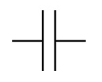
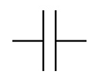
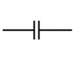
In a common schematic style, a basic capacitor is drawn as two parallel plates with a small gap between them. Wires connect the symbol to the rest of the circuit.
You may also see a reference label such as C1, C2, or C3. The letter C is commonly used to identify capacitors, while the number helps distinguish one component from another.
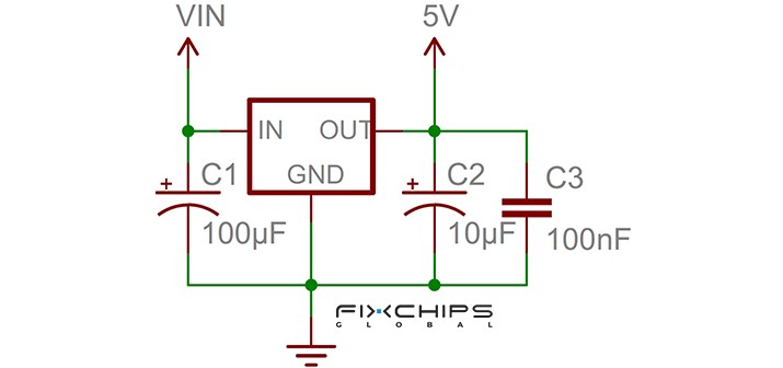
A circuit diagram may show several types of information near the symbol:
- Reference label: Identifies the capacitor in the circuit.
- Capacitance value: Shows its capacitance, such as 100 nF or 10 µF.
- Voltage rating: May be listed as a required component specification.
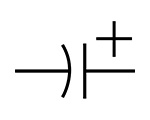
- Polarity mark: Indicates a positive terminal when the capacitor is polarized.
- Extra symbol marks: May indicate adjustable capacitance or another special feature.
Note: Not every schematic includes all these details. If information is missing, check the component list or circuit documentation.
Common Capacitor Symbols
Capacitor symbols can show basic component types or add information about special features. The most useful first step is to identify the basic shape and then check for extra markings.
Non-Polarized Capacitor Symbol
A common non-polarized capacitor symbol has two straight, parallel plates. It does not mark a fixed positive or negative terminal.
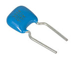
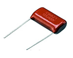
Ceramic and film capacitors often use this symbol. These components are widely used for filtering, bypassing, coupling, and timing.

Polarized Capacitor Symbol
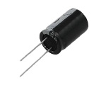
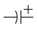
A polarized capacitor symbol may include a plus sign or a modified plate. The exact appearance depends on the drawing convention.
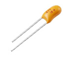
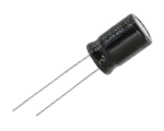
Aluminum electrolytic and many tantalum capacitors are polarized. Their terminals must be connected with the correct polarity when used in their intended circuits.
For example, a polarized capacitor used to smooth a DC power supply must be installed according to the circuit's positive and negative connections.

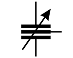
Variable Capacitor Symbol
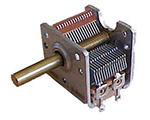
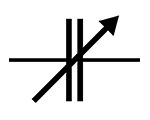
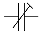
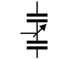
A variable capacitor symbol commonly uses a diagonal arrow across or near the basic capacitor symbol.
The arrow indicates that the capacitance can be adjusted. Changing the capacitance changes how the component responds to an AC signal.
Variable capacitors are used in some tuning and matching circuits, including radio-frequency applications.

Trimmer Capacitor Symbol
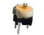
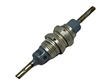
A trimmer capacitor is designed for small adjustments during setup or calibration. It is not usually intended for frequent user adjustment.
Its symbol consists of two parallel lines, intersected by a diagonal line with a crossbar at the top.
Trimmer capacitors are useful when a circuit needs a small capacitance correction to meet its target performance.

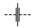
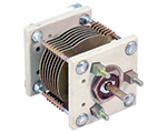
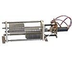
Quick Lookup Table for Common Capacitor Symbols
Some capacitors have special designs or uses. Their symbols may include extra details, or they may use a basic capacitor symbol with supporting labels.
|
Capacitor Type | Image | Symbol |
|
|
| |
|
|
| |
|
|
| |
|
|
| |
|
Variable Capacitor |
|
|
|
|
| |
|
|
| |
|
|
| |
| Butterfly Capacitor |
|
|
| Differential Capacitor |
|
|
How to Read Markings on Capacitors
A capacitor symbol tells you where the component is connected. Its markings tell you more about which component the circuit requires.
Capacitance Value
Capacitance measures how much electric charge a capacitor stores for a given voltage. It is represented by C and measured in farads (F).
Common units include:
|
Unit |
Symbol |
Conversion |
Common Uses |
|
Farad |
F |
1 F |
Large capacitance values and energy storage |
|
Microfarad |
µF |
1 µF = 10⁻⁶ F |
Power supply filtering and smoothing |
|
Nanofarad |
nF |
1 nF = 10⁻⁹ F |
Filtering and timing |
|
Picofarad |
pF |
1 pF = 10⁻¹² F |
RF and tuning circuits |
Note: Small components may use short numeric codes instead of printing the full capacitance value. If a code is unclear, check the manufacturer's datasheet rather than guessing.
Voltage Rating
The voltage rating is the maximum specified operating voltage under the conditions given in the component datasheet. The correct rating depends on the capacitor type and the circuit conditions.
A capacitor marked 25 V is not automatically suitable for every circuit operating below 25 V. AC voltage, voltage spikes, temperature, and the manufacturer's operating limits may also matter.
Tolerance and Other Markings
Some capacitors include a tolerance, which describes the allowed difference between the stated capacitance and its actual value under specified conditions.
Other markings may identify the manufacturer, series, date code, or safety approval. Their meaning depends on the component and its marking system.
How to Identify a Capacitor Symbol in a Circuit
Follow these steps to identify a capacitor in a schematic.
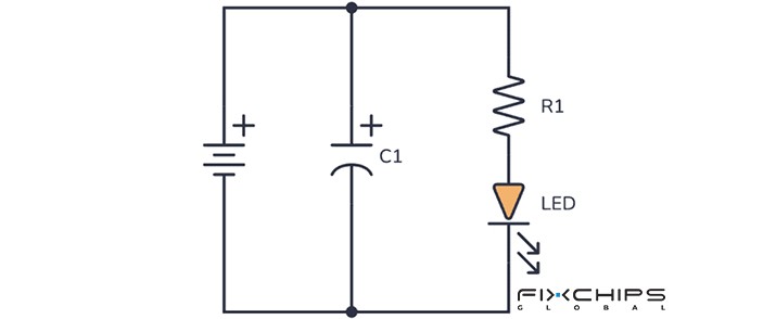
Step 1: Look for the Basic Shape
Find two plates separated by a small gap. This is the common starting point for recognizing a capacitor symbol.
Step 2: Check for Polarity Marks
Look for a plus sign or another indication of polarity. If the symbol shows polarity, check which terminal must connect to the positive side.
Step 3: Look for Extra Marks
A diagonal arrow often indicates adjustable capacitance. Other marks may identify a specialized component or a particular drawing convention.
Check the schematic legend if the meaning is unclear.
Step 4: Read the Reference Label and Value
Capacitors are commonly labeled with C followed by a number, such as C1 or C2.
The drawing may also show a capacitance value, such as 100 nF or 10 µF. Check whether a voltage rating or tolerance is listed as well.
Step 5: Check the Surrounding Components
Look at the components connected to the capacitor. Its position may suggest whether it is used for filtering, bypassing, coupling, timing, or voltage smoothing.
This is a useful clue, but it does not prove the capacitor's function by itself.
How Do Capacitors Work in Real Circuits?
Understanding where a capacitor is connected often helps explain why it is used.
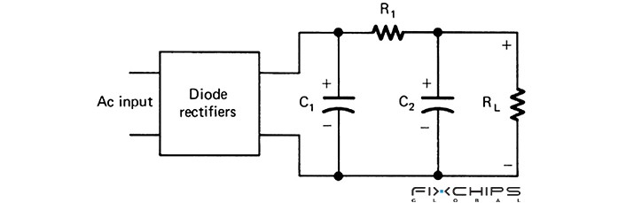
Power Supply Filtering
A power supply may use capacitors to reduce unwanted voltage changes. A larger capacitor can help smooth low-frequency ripple, while smaller capacitors placed near electronic devices can help reduce high-frequency noise.
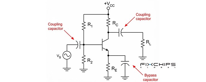
Signal Coupling
In some signal circuits, a capacitor passes changing signals between stages while blocking steady DC. This can help keep the DC operating conditions of each stage separate.
The capacitance must suit the signal frequency and the surrounding circuit. A value that works well at one frequency may reduce lower-frequency signals more strongly.

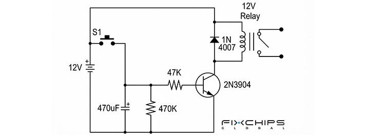
Timing Circuits
A capacitor can charge and discharge through a resistor. The voltage changes over time, so the combination can help set a delay or timing interval.
The timing depends on the resistance, capacitance, circuit design, and the voltage levels used to trigger the circuit.
Noise Bypassing
A bypass capacitor is often connected between a power rail and ground. It provides a path for certain unwanted AC signals and noise, helping keep the local supply voltage more stable.
This is why small capacitors are often placed close to the power pins of integrated circuits. Placement and connection layout can affect how well they work.
How to Test a Capacitor with a Multimeter
|
Step |
What to Do |
What to Check |
|
1. Inspect |
Look at the capacitor body and terminals |
Check for bulging, leakage, cracks, or damage |
|
2. Disconnect Power |
Turn off and isolate the equipment from its power source |
Make sure the circuit is no longer energized |
|
3. Discharge |
Use a suitable resistor to discharge the capacitor |
Verify the remaining voltage with a meter |
|
4. Isolate the Capacitor |
Remove the capacitor or disconnect at least one lead when practical |
Reduce measurement errors caused by other circuit components |
|
5. Select Capacitance Mode |
Set the multimeter to its capacitance function |
Confirm that the meter supports the expected value range |
|
6. Connect the Probes |
Connect the probes across the capacitor terminals |
Observe polarity for polarized capacitors and follow the meter manual |
|
7. Read the Result |
Wait for the reading to stabilize |
Compare the measured value with the rated value and stated tolerance |
Frequently Asked Questions
What does a capacitor symbol look like?
A common capacitor symbol consists of two parallel plates separated by a gap. Extra marks may indicate polarity or adjustable capacitance. The exact form can depend on the schematic convention.
Why do capacitor symbols look different?
Different symbols can indicate polarity, adjustability, or a specialized component. Some differences also come from regional or industry drawing conventions. Check the schematic legend or the referenced standard when the meaning is uncertain.
What is the main function of a capacitor?
A capacitor stores electrical energy in an electric field and can release that energy when needed. Depending on the circuit, it can also help filter noise, couple signals, smooth voltage, or control timing.
What is the difference between µF, nF, and pF?
These are units of capacitance. One microfarad equals 1,000 nanofarads, and one nanofarad equals 1,000 picofarads.
How can you identify a capacitor in a circuit diagram?
Look for the basic capacitor symbol, which commonly has two plates separated by a gap. Then read its reference label and value, check for polarity marks, and follow its connections to nearby components.
Related Articles
How to Choose the Right AC Capacitor? A Complete Guide
MLCC - Types, Electrical Properties, and Selection
What Is a Variable Capacitor? Types, Uses and Working Principle


