



Introduction
A Manifold Absolute Pressure (MAP) Sensor acts as the engine's "respiratory monitor," accurately measuring intake air volume to keep the engine running efficiently and save fuel.
This article offers a clear, concise guide to its functions, internal structure, and troubleshooting steps.
What is a MAP Sensor?
A MAP Sensor is a compact electronic component designed to measure air pressure inside the engine intake system. Typically mounted directly on the intake manifold, it detects real-time pressure fluctuations. By sending this pressure data to the Engine Control Unit (ECU), it helps calculate the exact fuel amount needed for smooth engine performance.
Functions of MAP Sensor
- Provides intake pressure data: It gives the ECU information about pressure inside the intake manifold.
- Supports fuel control: The ECU uses MAP data when calculating the required fuel amount.
- Supports ignition control: MAP information helps the ECU adjust ignition timing according to engine load.
- Supports engine load detection: Changes in manifold pressure provide information about how hard the engine is working.
The Structure of MAP Sensor
The internal construction of a MAP sensor is highly precise, consisting of several essential core components.
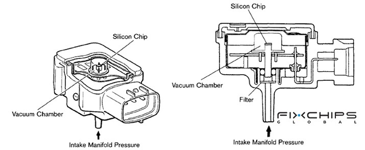
- Housing: Protects the internal sensor parts and provides the physical structure for installation on the engine.
- Pressure Port: Provides a path for intake manifold pressure to reach the sensing element.
- Silicon Chip: The diaphragm bends when pressure changes, allowing the sensor to detect changes in intake pressure.
- Reference Chamber: Provides a known pressure reference for measuring the pressure applied to the sensing element.
- Electrical Connector: Connects the MAP sensor to the vehicle wiring and allows power and sensor signals to pass between the sensor and the engine control system.
How to Find the MAP Sensor?
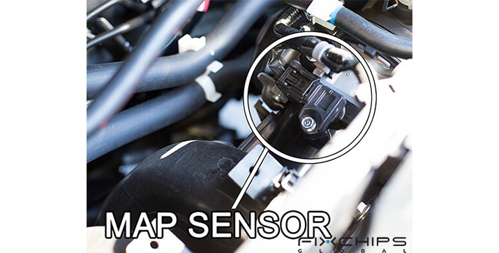
To locate the MAP Sensor, open the hood and inspect the intake manifold above the engine block.
It is usually mounted directly onto the manifold or connected via a short black rubber vacuum hose. At the back of the sensor, you will find an electrical connector attached to a wire harness that runs directly to the vehicle's ECU.
Working Principle of MAP Sensor
A MAP sensor turns a change in air pressure into an electrical signal. When manifold pressure changes, the silicon chip changes shape, which changes the electrical resistance of the sensing element.
The ECU receives this signal and uses it with other engine information. For example, pressure changes caused by throttle position, engine speed, or turbo operation can help the ECU determine engine load and adjust fuel and ignition control.
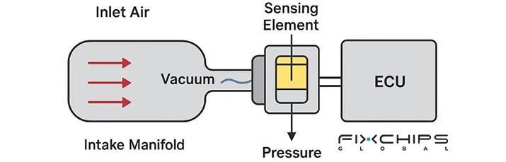
In simple terms, the process is:
Intake pressure changes → sensing element responds → electrical signal changes → ECU reads the signal → engine control is adjusted.
Specifications of MAP Sensor
To better understand its technical characteristics, below is a specification table for standard MAP Sensors:
|
Specification |
Typical Value / Parameter |
|
Operating Voltage |
5.0 V DC |
|
Output Voltage Range |
0.5 V to 4.5 V |
|
Operating Temperature |
-40°C to +125°C |
|
Response Time |
< 2 ms |
|
Output Signal |
Analog voltage or digital frequency pulse |
|
Input Current |
< 10 mA |
|
Connector Type |
3-pin weatherproof plug |
|
Weight |
Approx. 20 to 40 g |
Types of MAP Sensor
MAP Sensors can be classified into different categories based on their output signals and pressure references.
Classified by Output Signal
Based on the signal format transmitted to the ECU, MAP sensors are divided into two main types:
Analog MAP Sensor
This sensor outputs a continuously variable voltage signal. Composed of basic sensing elements and amplifier circuits, it is widely used in conventional fuel-injection systems.
As intake pressure increases, the output voltage rises smoothly, allowing the ECU to read pressure levels directly.

Digital MAP Sensor
This sensor outputs a series of digital pulses or frequency signals. Equipped with an internal microprocessor, it converts pressure into digital data with exceptional noise resistance.
Commonly used in modern advanced vehicles, it delivers faster and more precise data transmission.

Classified by Pressure Reference
Based on the reference point used to measure pressure, sensors are categorized as follows:
Absolute MAP Sensor
This type measures pressure against a complete vacuum inside the sensor. Made of a vacuum chamber and a silicon chip, its readings remain unaffected by ambient weather or altitude.
It is the most common type in modern vehicles, used for precise absolute air intake calculation.

Gauge/Relative Pressure MAP Sensor
This sensor measures pressure relative to local ambient atmospheric pressure. As external atmospheric pressure changes, its baseline measurement shifts accordingly.
It is typically applied in specialized industrial equipment or specific turbocharger monitoring systems.

Differential Pressure MAP Sensor
This sensor connects to two separate pressure ports and measures the pressure difference between them. Featuring dual intake ports, it computes results by comparing pressure on both sides.
In automotive applications, it is commonly used in Diesel Particulate Filter (DPF) or exhaust monitoring systems.

The Symptoms of a Faulty MAP Sensor and How to Replace
Promptly identifying and replacing a faulty MAP Sensor is crucial, as driving with a damaged sensor can cause severe engine wear and sharp increases in fuel consumption.
Symptoms of a Faulty MAP Sensor
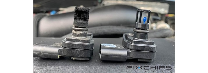
- Check Engine Light Illuminates: The ECU receives out-of-range sensor readings and triggers a fault code.
- Poor Fuel Economy: Incorrect high-pressure readings cause the ECU to inject excessive fuel.
- Rough Idling or Stalling: Inaccurate air data disrupts the air-fuel ratio, preventing smooth idle operation.
- Hesitation During Acceleration: The ECU fails to deliver extra fuel when pressing the gas pedal, leading to power loss.
- Black Exhaust Smoke: Unburned excess fuel from incomplete combustion is discharged through the tailpipe.
How to Replace a Bad MAP Sensor?
Replacing a faulty sensor quickly restores engine efficiency; for safety, repairs should be performed by individuals with basic automotive knowledge or professional technicians.
1. Locate the sensor: Find the MAP sensor on or near the intake manifold.
2. Inspect the sensor: Check the sensor, wiring, connector, and pressure hose for visible damage.
3. Disconnect the electrical connector: Release the locking mechanism before removing the connector.
4. Remove the sensor: Remove the screws or bolts holding the sensor in place.
5. Compare the replacement: Check that the new sensor matches the old sensor and vehicle application.
6. Install the new sensor: Connect the hose if required and position the sensor correctly.
7. Reconnect the electrical connector: Make sure the connector is fully locked.
8. Check the installation: Confirm that the sensor, hose, connector, and fasteners are secure.
How to Maintain a MAP Sensor?
A. Periodically check the connecting rubber vacuum hose to ensure it is free from cracking, hardening, or leaks.
B. Keep the electrical connector clean and dry to prevent poor contacts caused by oil or moisture accumulation.
C. Replace the engine air filter regularly to prevent dust buildup in the intake manifold from contaminating the sensor probe.
How to Test a MAP Sensor?
Testing can help separate a faulty sensor from problems in the wiring, connector, or pressure hose. A digital multimeter, vacuum pump, and diagnostic scan tool may be used depending on the vehicle and sensor design.
|
Step |
Description |
|
1. Inspect the sensor |
Check the MAP sensor, connector, wiring, and pressure hose for visible damage or contamination. |
|
2. Check the electrical connection |
Use the vehicle service information to identify the correct power, ground, and signal connections. |
|
3. Check the supply voltage |
Use a digital multimeter to confirm that the sensor receives the required supply voltage. |
|
4. Check the output signal |
Measure the sensor output and compare it with the manufacturer's specifications. |
|
5. Apply pressure change |
Use a suitable vacuum pump when the sensor design and service procedure allow this test. |
|
6. Observe the signal |
The output should change in response to the applied pressure change. |
|
7. Use a scan tool |
Read the MAP value through the vehicle diagnostic system and compare the reading with expected conditions. |
|
8. Confirm the result |
If the signal is missing, unstable, or outside the specified range, continue diagnosis before replacing the sensor. |
MAP Sensor vs MAF Sensor
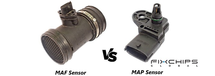
Although both MAP Sensors and MAF Sensors help the engine computer monitor intake air, their working principles and operational focuses differ significantly.
|
Feature |
MAP Sensor |
MAF Sensor |
|
Function |
Measures manifold pressure |
measures the mass and flow rate of air entering the engine. |
|
Location |
Mounted on the intake manifold or connected via a vacuum hose. |
Installed on the intake pipe between the air filter box and throttle body. |
|
Weight |
Lightweight, typically 20 to 40 grams. |
Heavier, 100 to 300 grams. |
|
Accuracy |
Relies on calculated estimates. |
Highly accurate physical measurements. |
|
Advantages |
Simple structure, low cost, highly resistant to dust and light oil contamination. |
Direct measurements eliminate complex calculations by the ECU. |
|
Disadvantages |
Readings become inaccurate if valve leaks or exhaust blockages occur. |
Fragile internal hot-wire elements are easily contaminated by dirt. |
|
Lifespan |
Highly durable. |
Shorter lifespan |
|
Applications |
Engine management, intake-pressure and boost-pressure measurement |
Engine air-flow measurement and engine management |
Frequently Asked Questions
What is the main role of a MAP Sensor?
A MAP sensor measures the pressure inside the engine intake manifold and sends this information to the engine control unit (ECU). The ECU uses the data to help calculate the air mass and control fuel delivery and ignition timing.
Is it necessary to use both MAP and MAF sensors?
No, an engine does not always need both sensors. Some engines use a MAP sensor, some use a MAF sensor, while some systems, especially certain turbocharged engines, use both.
Will an engine work without a MAP sensor?
It depends on the engine's control system. Some engines mainly use a MAF sensor instead of a MAP sensor, while systems that depend on MAP data may have poor fuel control and engine performance if the MAP signal is missing or inaccurate.
How long does a MAP sensor usually last?
There is no fixed service life for all MAP sensors. Their condition can be affected by contamination, damaged hoses, vibration, wiring problems, and heat, so replacement is normally based on the sensor's condition and test results rather than a set time or mileage.
How can you check a MAP sensor at home?
You can first inspect the sensor, connector, wiring, and hose for damage or contamination. With suitable tools such as a digital multimeter and hand vacuum pump, you can check the reference voltage and observe whether the sensor voltage changes steadily as vacuum increases.


